Introduction
State machines are one of the fundamental organizing principles behind video games. Game developers usually encounter state machines early in their learning journey. It feels natural, the implementation is straightforward, and it can be used effectively without knowing what a state machine actually is. That understanding starts to matter when the system you are designing grows more complex.
This article builds that foundation, drawing from two main sources: the Finite State Machine from automata theory1, and the State Pattern from the Gang of Four2 (shortened, GoF).
Anatomy of a State Machine
When we talk about finite state machines in the context of video games, what we usually mean is the deterministic variant of finite state machines, Deterministic Finite Automaton (DFA). The “deterministic” part is the key here. A transition from a given state under given conditions always leads to exactly one state. Non-deterministic Finite Automaton (NFA), where the same input can lead to multiple possible states, is rarely used in game development.
Components of a State Machine
Three core components define a state machine.
-
States: a specific set of behaviors that the state machine performs at a given moment.
-
Initial State: the state the state machine begins in.
-
Transition: the change from one state to another, occurring when an input is received and any required conditions are met.
Note that “input” doesn’t literally mean “user input” here. It refers to any signal the state machine responds to, such as a key press, the end of an animation, a timer reaching a threshold, a collision etc.
Comparison with DFA
A Deterministic Finite Automaton (DFA) can be expressed in the 5-tuple notation:
where
- : finite set of states.
- : finite set of input symbols.
- : transition function that takes as arguments a state and an input symbol and returns a state.
- : the starting state; .
- : set of final or accepting states; .
Notice that and are absent from our definition of a state machine. is implicitly defined within the transitions rather than declared separately. is omitted entirely, because a set of final states rarely has meaningful application in video games.
State Diagram
The components of a state machine can be represented using a directed graph, where nodes represent states, and edges represent transitions. This representation is called the state diagram, or state graph.
The diagram gives us a structural view of the whole system - which states exist, how they are connected, and under what conditions the transitions occur - without showing the behavior inside each state.
In a state diagram, states are represented as circles and transitions as directed edges between them. The initial state is usually marked with a double ring or an incoming arrow.

Double ring notation
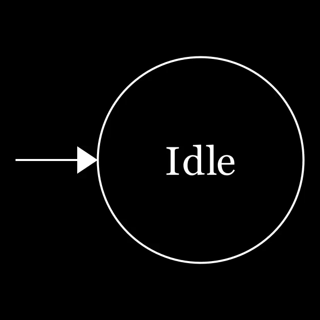
Incoming arrow notation
Each edge is labeled with the name of the transition that triggers it.
Here is an example.
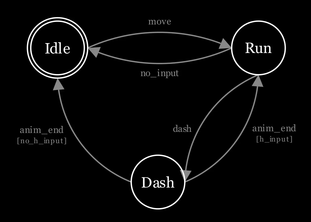
The state diagram shows three states - Idle, Run and Dash. Idle is the initial state, marked with a double ring. Each arrow is a transition, labeled with the input that triggers it. The anim_end transitions from Dash have conditions written in square brackets. [h_input] if the left or right key is held, [no_h_input] if not. We will look at conditions in more detail later.
Now let’s see it in action.
The video shows a player character in-game at the top and the corresponding state diagram at the bottom. At the bottom left corner, you can see the keyboard input that’s being pressed. Each transition is highlighted as it triggers. The active state is highlighted.
The player starts in the Idle state. Pressing right triggers a transition into Run. Pressing space triggers a transition into Dash. Once the dash animation completes, the state machine returns to Run when the right key is held. Otherwise, it moves back to Idle.
We are going to use state diagram as the primary mental model for state machines.
State
A state represents a specific set of behaviors that the state machine performs at a given moment. In the state diagram, states are represented as nodes.
Properties of States
-
A state is encapsulated. It is essentially a black box to the outside world. No other state, nor the transitions between them, need to know what happens inside a state. This property makes the state machine scale very well. A state can be added, removed or modified in isolation without affecting the internal implementation of other states.
The Idle and Run states don’t know that the Dash state makes the player invincible.
-
A state machine can be in exactly one state at a given moment. The state machine starts at one state, and subsequent transitions always lead to exactly one state. So the state machine always stays with a single active state.
-
The active state controls the behavior of the state machine. The state machine itself contains minimal behavioral logic; most of the system’s behavior is delegated to the active state. This is precisely captured in the intent of the State pattern defined by GoF:
Allow an object to alter its behavior when its internal state changes. The object will appear to change its class.
When the state of an object changes, an observer watching the object would think it has suddenly become a different object entirely. In our example, the player stays still in the Idle state, but moves in the Run state, and has a burst of speed in the Dash state. Each state plays different animations. Even though it is the same object, it exhibits completely different behavior as the state changes.
Lifecycle of a State
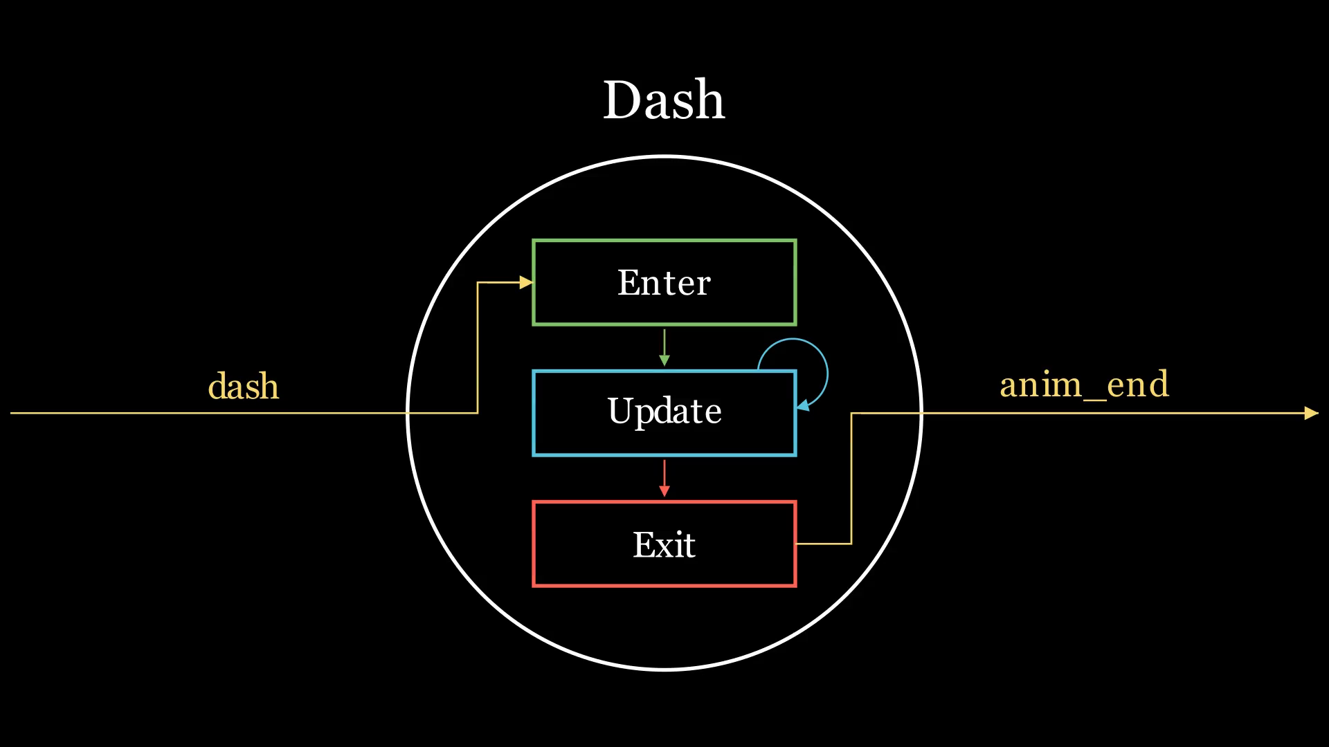
A state has three distinct phases during its lifetime.
-
Enter: Executed once, the moment the state machine transitions into the state.
This is where the setup happens. Anything that is needed for the duration of the state gets initialized here. For example, the Dash state makes the player invincible here.
-
Update: Executed at a fixed interval (usually once per game loop), as long as the state machine remains in the state.
This is where we define the ongoing behavior of the state. For example, during the Dash state, the player moves with a velocity that decreases once every game loop.
-
Exit: Executed once, the moment the state machine transitions out of the state.
This is where the cleanup happens. Anything initialized in Enter gets undone here. For example, the Dash state removes the player’s invincibility here.
Naming Conventions
Different engines and frameworks use different names for these three phases, but the lifecycle is always the same.
- Enter is also called onEnter, Begin, Start, Activate, or Create.
- Update is also called OnUpdate, Tick, Step, or Execute.
- Exit is also called OnExit, Leave, End, Stop, Deactivate, or Destroy.
Notice that Enter and Exit are mirrors of each other. Anything set up in Enter is discarded in Exit. This symmetry is essential in keeping states self-contained. The state machine is always in a valid configuration before entering and after exiting a state.
Initial State
The initial state is the state the state machine begins in. In the state diagram, it is usually represented as a node with a double ring or with an incoming arrow. In our example, it is the Idle state.
Every state machine must have exactly one initial state. This follows from property 2 of states: since the state machine must be in exactly one state, it must begin in exactly one state.
The initial state has no special significance in any other way. It has the same properties and lifecycle as other states, and can be transitioned in or out of like any other state.
Transition
A transition is the change from one state to another. In the state diagram, transitions are represented as directed edges between nodes. The edge points from the source state to the destination state, with the name of the input that triggers it.
Transitions define the structure of the state machine. Without them, a state machine is just a collection of isolated states with no way to move between them. The transitions determine the state of a state machine under given conditions.
When an input is received, the state machine evaluates the outgoing transitions of the active state and deterministically selects the one whose input and condition are satisfied, if any.
Conditions in Transitions
A transition does not fire unconditionally. A condition is a requirement that must be satisfied for a transition to occur. If the condition is not met, the transition does not fire, even if the input is received.
In practice, conditions are not always explicitly declared. A transition defined without a condition acts as if there is a condition that always evaluates to true.
In the state diagram, conditions are written alongside the transition label on the edge, inside square brackets.
In our example, anim_end [h_input] and anim_end [no_h_input] are examples of transitions with conditions, where [h_input] and [no_h_input] are the conditions.
What does the square bracket mean?
The square bracket notation comes from Iverson brackets - a convention in mathematics where [P] is 1 if P is true and 0 otherwise. In a state diagram, [condition] means the transition fires only when the condition evaluates to true.
Structure of Transitions
Each transition is defined by four elements.
- Input: the signal that triggers the transition. It is what the state machine listens for while in the source state. This is also referred to as “Trigger”.
- Source State: the state the state machine is currently in when the transition occurs.
- Destination State: the state the state machine enters after the transition occurs.
- Condition: the requirement that must be satisfied for the transition to occur.
Properties of Transitions
-
Transitions are deterministic. A transition from a state under given conditions should always transition to exactly one destination state - the same destination state, every time.
This property is what makes state machines deterministic. Just as a DFA always produces the same result for the same input sequence, a state machine always produces the same next state for the same input and conditions.
Each transition is uniquely identified by the tuple (input, source state, condition), which determines a single destination state.
-
Transitions are directed. The existence of a transition from state A to state B does not imply that there is also a transition from state B to state A. Self-loops are allowed in transitions - a state can transition into itself.
-
Not every input needs a transition. If an input arrives and no transition is defined for it in the current state, nothing happens. The state machine stays where it is.
-
Transitions are instantaneous. A transition has no duration. The state machine exits the source state and immediately enters the destination state. It means that the Exit phase of the source state and Enter phase of the new state execute back-to-back, with no game logic running between them.
Any behavior that needs to happen over time belongs inside a state, not a transition.
The Theory
A state machine is defined by these three components: states, transitions, and the initial state. Every state machine, no matter how large, reduces to these three components. That’s the entire theory.
States are the hardest to get right. Knowing only what a state is doesn’t tell you which things in your game deserve to be states.
Defining State Boundaries
Designing a state machine begins with identifying the states. That sounds straightforward until you find yourself staring at two candidates, unsure whether they are one state or two. This is not a rare edge case. This is the kind of decision that come up in almost every non-trivial state machine.
State boundaries are design decisions. Sometimes, there is no single correct answer to a specific situation. What matters is to have a consistent tool for making the decision, so that the choices we make hold up as the system grows.
States and Data
A state defines what the system does - what it executes every frame, what it does upon entering and exiting, what inputs it responds to. A state is not defined by the data it holds. Two state candidates that differ only by the data they hold are not two states. They are one state with different values.
A player moves at speed 5 on grass and speed 3 on mud. Are these two states? The speed is a value that the state holds, not a property that defines the state. Perhaps they play different animations - walking on grass plays a regular walk cycle, whereas walking on mud plays a slogging walk cycle. The animation is data too. Neither the speed nor the animation changes which transitions are available, so neither defines a state boundary. Walking is one state.
A player faces left when moving left, and right when moving right. Moving left and right are not different states, they are the same state, differentiated by a variable that determines what direction the player is facing.
Data includes, but is not limited to: speed, direction, scale, sprite, animation, color, health, a flag, a counter, a timer. Any value a state holds internally that can change without changing which transitions are available is data, not behavior. A state boundary exists where the behavior changes - where the system begins responding differently to the world.
The Behavioral Test
The most reliable way to define state boundaries is to compare transition rules. Two candidates are one state if they are entered the same way, exited under the same conditions, and respond identically to every input while active. If any of those three differ, they are likely two states.
This is the behavioral test. We will use it as the primary tool for defining state boundaries.
Conventions
Even though the behavioral test is the most reliable tool for defining state boundaries, it is not always the fastest, and sometimes it’s just not practical. The following conventions are often used to draw state boundaries:
-
The Animation Convention (One Animation, One State)
If two candidates play different animations, they are different states.
The convention is very intuitive because animations are the most tangible manifestation of a state, and different animations are often created where behavioral differences exist. Run and Dash look different, so they are different states. The behavioral test agrees because their transition rules differ.
-
The Action Convention (One Action, One State)
If the system is doing something distinct and nameable, it deserves its own state.
This convention maps states to gameplay verbs - running, jumping, blocking. It is closer to the behavioral test because verbs describe behavior, not appearance. Jumping pushes the character upwards, and running pushes the character sideways. So Jump and Run are different states.
The conventions are useful starting points. They are fast to apply and produce correct results in most cases. But they do not always work - for example, when the animation or the action varies without the behavior changing, or when two things look or sound the same but behave differently. This is when the behavioral test gives us a consistent answer.
Where Conventions Break
Consider the following cases:
-
A player has multiple emotes - waving, dancing, looking around. Each emote has a different animation. The animation convention suggests that they are different states. The player is “emoting” - that’s a verb describing what they are doing. So the action convention suggests that this is one state.
-
A player can jump while floating in the air (commonly known as air-jump). There are two state candidates: ground-jump and air-jump. Imagine they are using the same ascending animation. The animation convention says they are one state. The action convention sees two distinct verbs and says that they should be two states.
Let’s apply the behavioral test to the two cases above.
For case 1, all transitions are entered (triggered from Idle by selecting an emote) and exited the same way (user input triggered, or the animation ends). They respond identically while active. By the behavioral test, this is one state - call it Emote - with specific animation played as data.
For case 2, ground-jump and air-jump are both entered by the jump input, and both play the same ascending animation. It’s tempting to say the only difference between them is a counter tracking the remaining air jumps - just decrement it on use, and call it one Jump state. But a counter is only data if it doesn’t change which transitions are available. Here, it does. Ground-jump has no self-loop (no transition from Ground-jump back to itself). Once airborne, jump input does nothing until the player lands. Air-jump does have a self-loop, conditioned on a counter being positive. Since one candidate has a transition the other structurally cannot have, by the behavioral test, these are two states.
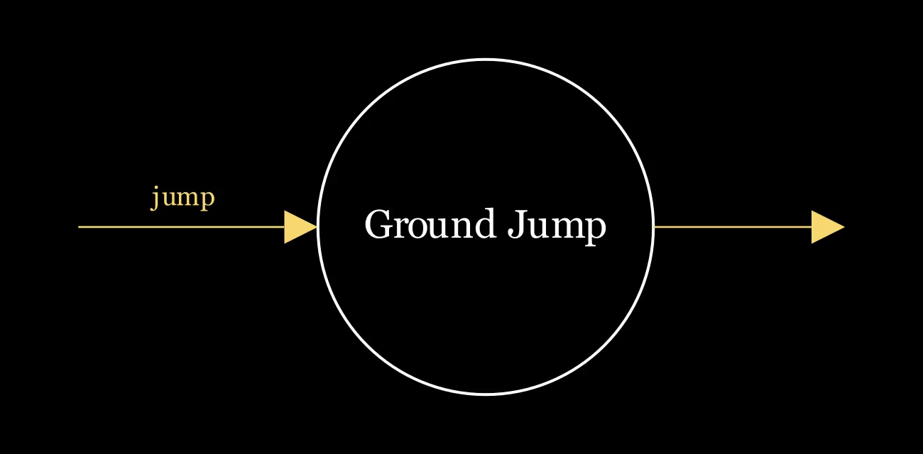
Ground Jump: entered via jump, exits to other states
![State diagram for Air Jump: same inbound and outbound transitions as Ground Jump, plus a conditional self-loop labeled jump [air_jumps > 0]](/_assets/air-jump-state-diagram.D_lo7IqT.png)
Air Jump: identical to Ground Jump except the conditional self-loop
The two conventions disagreed with each other, and they disagreed with the behavioral test. This is exactly why having a consistent tool matters. You could pick a convention and apply it everywhere. But conventions are proxies. Animation is a proxy for behavior, and so are verbs. The behavioral test looks at transitions directly, instead of inferring them from what a state looks like or what it’s called.
Conclusion
We have learned two things. The first is what state machines are made of: states, transitions, and an initial state. Every design decision traces back to these three components. The second is how to define state boundaries. The conventions work most of the time, and there is nothing wrong with using them. The behavioral test is what we can refer to when they don’t. Having a consistent tool in our pockets means we never get stuck.
Congratulations! You now have the foundations needed to design state machines with confidence.